
Pulse carriageway 1 & 4 locking and and unlocking instructionsIntroduction and ScopeThis method statement provides step-by-step instructions for the safe opening, closing, and basic maintenance of the security variant of Pulse Carriageway 1 and 4 frames and covers. It is intended to support product handover, ongoing operational use, and ensure compliance with site standards. All operations described in this document must be carried out in strict accordance with:
All lifting of covers must follow HSE guidance on safe working loads and approved lifting techniques. Unit identification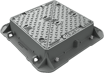
Pulse / BT Carriageway 1 Security
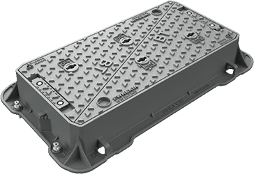
Pulse / BT Carriageway 4 Security
Unlocking - Step 1 - Identify Locking PointsLocate the padlock housing sub-covers. Each triangular cover has one padlock housing, as shown circled in the image. 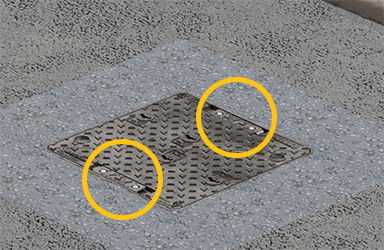
Unlocking - Step 2 - Remove Sub-Cover BoltsUsing a 17mm socket, remove the 2x ISO 4016 - M10 x 25 bolts securing each padlock housing sub-cover. 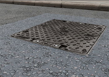
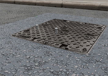
Unlocking - Step 3 - Disengage Sub-Cover EngagementHinge open the Sub cover to allow access to the padlock housing in the main cover below. 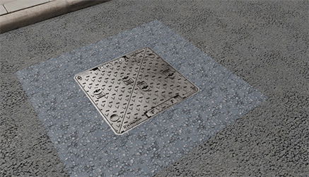
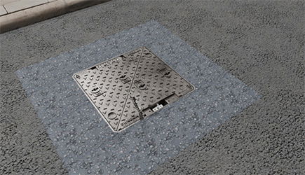
Unlocking - Step 4 - Unlock and Remove PadlockUse the Pulse / BT padlock key to unlock and remove the padlock body completely. The padlock shackle will remain in place in the housing. 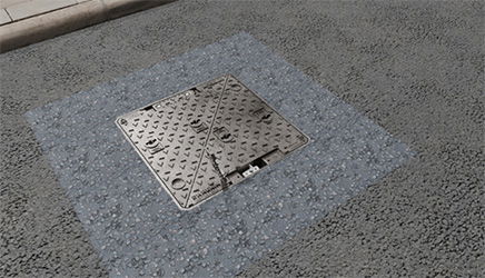
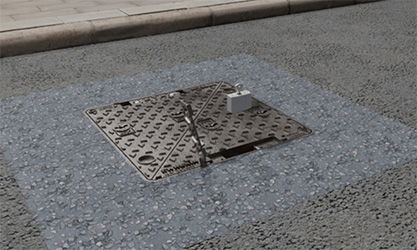
Unlocking - Step 5 - Remove CoversOnce both padlocks have been removed from a pair of covers, the covers can be lifted out following HSE standard cover handling process. 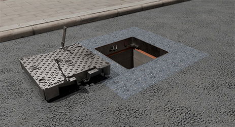
Unlocking - Step 6 - Remove Padlock Shackle from FrameRemove the padlock shackle from the frame-mounted hinged lock arm and place somewhere safe. 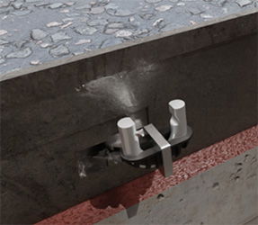
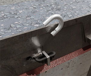
Unlocking - Step 7 - Hinge Closed the Frame-Mounted Lock ArmWith the padlock shackle removed, hinge the frame-mounted lock arm fully closed. This ensures the clear opening is completely unobstructed and ready for safe operator access. 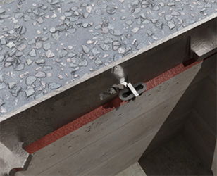
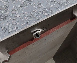
Locking - Step 1 - Open the Frame-Mounted Lock ArmRotate the frame-mounted hinged lock arm 90 degrees into its fixed open position. This ensures the arm is in the correct position and ready to receive the padlock shackle and covers during refitting. 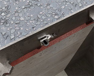
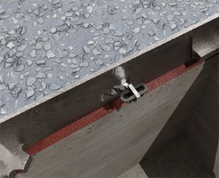
Locking - Step 2 - Insert Padlock ShacklePlace the padlock shackle into the rubber cradle on the frame-mounted hinged lock arm. Ensure the padlock shackle is positioned vertically within the cradle to allow proper alignment with the cover during refitting. 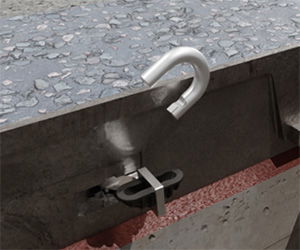
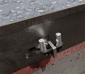
Locking - Step 3 - Refit Covers (in Coupled Pairs)Lift and lower the coupled pairs of triangular covers carefully back into the frame, following HSE standard cover fitting process. Important This is essential to allow the covers to be securely locked. Also, ensure the covers are replaced in the same orientation as they were removed. 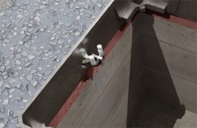
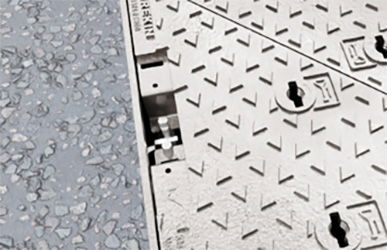
Locking - Step 4 - Reinstall PadlocksInsert the padlock body onto the exposed shackle and lock it securely using the Pulse / BT padlock key. Confirm the padlock is fully engaged and locked. 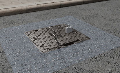
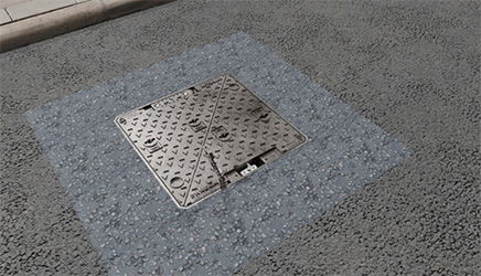
Locking - Step 5 - Close and Secure Sub-CoversHinge the padlock housing sub-covers back into their closed position. Secure each sub-cover down using 2x ISO 4016 - M10 x 25 bolts previously removed. Tighten using a 17mm socket. 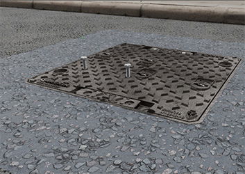
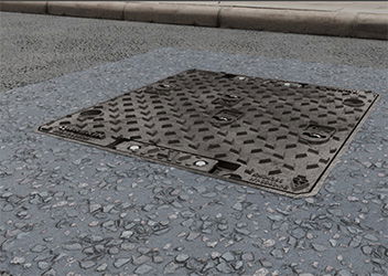
MaintenenceThe locking system is designed to be low maintenance. Routine Actions:
Related products
| ||||||||||||||||||||||||||||||||||||||||

