
ScrewLift installation instructionsProduct Overview & PPE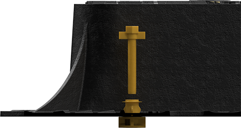
ScrewLift is our adjustable levelling system for ductile iron access covers and drainage gullies, supporting high-quality installations that reduce early-life failure and extend the whole-life duration of an installation.
ScrewLift componentsScrewLift is made of 2 components which we call:
Each ScrewLift pack also includes a recyclable/biodegradable string line for checking levels/camber of the frame against the road surround. Insert ScrewLift unit (skip for pre-fitted frames)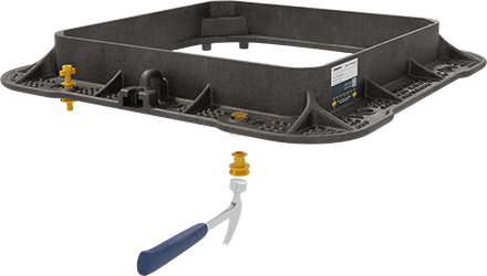
For retrofit applications, insert each single-piece ScrewLift base unit from the underside of the frame until it firmly locks into place by applying firm pressure from underneath or using a light tap from a hammer or mallet. Each frame should be fitted with 4x ScrewLift base units, with one situated close to each corner of the frame in a designated frame hole. Once the ScrewLift base units are in place, insert the ScrewLift levelling screws from the top. Note: Factory-fitted units include pre-installed base units and screws. You can skip to Step 3. Position the frame over the chamber opening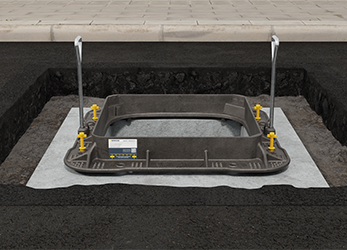
Carefully position the frame over the chamber’s clear opening using BS7903-compliant long-handled lifting keys. Our frames feature unique ergonomic lifting points for safer and more accurate placement. Ensure the flange is fully supported, no bridging, voids, or overhang. Safety: Do not place hands or fingers underneath ironwork unless the unit is securely supported and stable. Prepare for levelling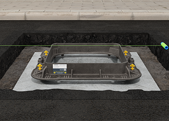
With the frame in position, check alignment using a string line or straight edge. Assess both direction of travel and crossfall to match road camber and gradient. Adjust the ScrewLift levelling screws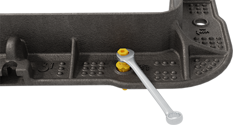
Adjust each ScrewLift levelling screw to raise or lower the frame using:
Work evenly until the frame sits flush with the surrounding surface. Tip: Pre-extend the levelling screws before placing the frame. Gravity then assists as you wind down. Confirm levelling accuracy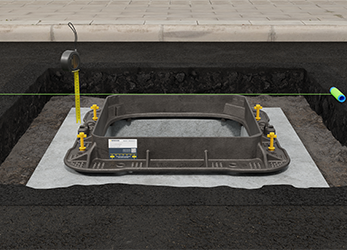
Re-check the frame across both axes to confirm it's level. Make final adjustments as needed to ensure the top of the frame is plum/level with the top road surface. Bedding mortar reminderBedding mortar must form a continuous bond between the frame and the chamber. The ScrewLift base unit guarantees a minimum 15mm thickness, required to maintain structural integrity and durability. This prevents insufficient bedding material, ensuring a stable, long-life installation. Related products
| |||||||||

