
Pulse carriageway 2 & 3 locking and and unlocking instructionsIntroduction and ScopeThis method statement provides step-by-step instructions for the safe opening, closing, and basic maintenance of the security variant of Pulse Carriageway 2 and 3 frames and covers. It is intended to support product handover, ongoing operational use, and ensure compliance with site standards. All operations described in this document must be carried out in strict accordance with:
All lifting of covers must follow HSE guidance on safe working loads and approved lifting techniques. Unit identification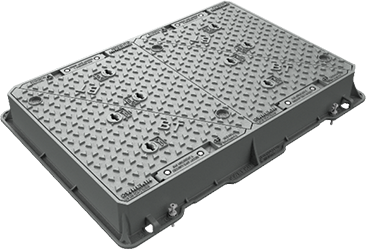
Pulse / BT Carriageway 2 Security
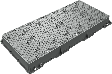
Pulse / BT Carriageway 3 Security
Unlocking - Step 1 - Identify Locking PointsLocate the padlock housing sub-covers. Each triangular cover has one padlock housing, as shown circled in the image. 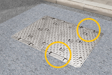
Unlocking - Step 2 - Remove Sub-Cover BoltsUsing a 17mm socket, remove the ISO 4016 - M10 x 25 bolts securing each padlock housing sub-cover. 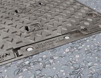
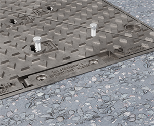
Unlocking - Step 3 - Disengage Sub-Cover EngagementUse a pry bar or flat-head screwdriver to carefully disengage the sub-cover engagement feature. This allows the sub-cover to hinge open, giving access to the padlock underneath. 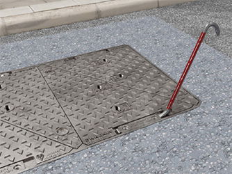
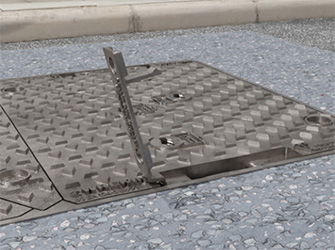
Unlocking - Step 4 - Unlock and Remove PadlockUse the Pulse / BT padlock key to unlock and remove the padlock body completely. The shackle will remain in place in the housing. 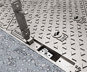
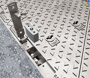
Unlocking - Step 5 - Remove CoversOnce both padlocks have been removed from a pair of covers, the covers can be lifted out following standard cover handling process.
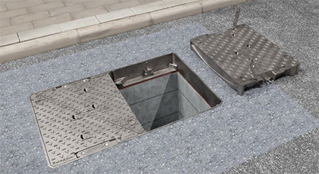
Locking - Step 1 - Refit Covers (in Coupled Pairs)Lift and lower the coupled pairs of triangular covers carefully back into the frame, following standard cover fitting process. Important This is essential to allow the covers to be securely locked. 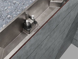
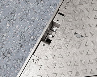
Locking - Step 2 - Reinstall PadlocksInsert the padlock body onto the exposed shackle and lock it securely using the BT padlock key. Confirm the padlock is fully engaged and locked. 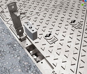

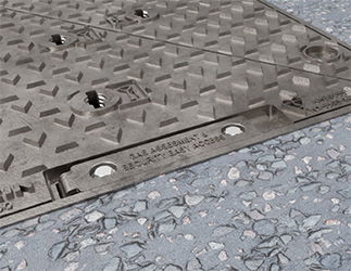
Locking - Step 3 - Close and Secure Sub-CoversHinge the padlock housing sub-covers back into their closed position. Apply firm pressure (by foot) onto the sub lid to ensure the spring retaining feature in the sub-lid engages when closed. Secure each sub-cover down using the ISO 4016 - M10 x 25 bolts previously removed. Tighten using a 17mm socket. 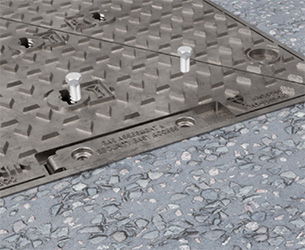
MaintenanceThe locking system is designed to be low maintenance. Routine Actions:
Related products
| ||||||||||||||||||||||||||||||||||||||||

