Home
My Wrekin
Geosynthetics being installed on site

CellTrack Heavy Duty (HD) installation guide

Grassed surfaces installation build up

Celltrack build up


Layer Material Thickness
1. Sub-grade Existing subgrade or capping layer  
2. Reinforcement Optional E'GRID 3030 geogrid or MultiTrack geotextile  
3. Compacted sub-base

Free-draining class 805 MoT Type 3 (open-graded) granular aggregate or;

Pipe-drained Class 803 MoT Type 1 Sub-base thickness from table 1

 
4. Separation MultiTrack 1000  
5. Bedding layer Compacted, clean, course grit sand bedding layer 20mm
6. Paver CellTrack HD 100mm or 120mm
7. Retaining Edge E.g kerb or edging stone  


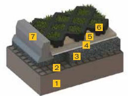
Grassed surfaces installation instructions

The following generic guidance must be read in conjuction with the specific project specification within the contract documents and the design notes below.

  1. Install the optional geogrid, geotextile and/or geomembrane onto the prepared subgrade formation.
  2. Install the specified sub-base layer and optional drainage.
  3. Install any edge restraints which may be specified. Timber, plastic or concrete kerbing are all suitable.
  4. Install the filter/separator geotextile on top of the subbase layer.
  5. Install the specified sand bedding layer to a uniform thickness.
  6. Ensure an accurate right-angled CellTrack HD laying pattern by setting out the site using string lines. Check the lines regularly for accuracy. Start installing the CellTrack HD pavers. Wherever possible start laying from a right-angled corner and progress across the site in rows. The pavers can be installed in a width or lengthwise orientation and cross-bonded if required or appropriate to fit the site. When installing the pavers, ensure that the male/female connectors are fully located together. Use protective gloves to avoid abrasions.
  7. CellTrack HD pavers can be cut to fit around obstructions & curves using a hand or power saw. Wherever possible avoid using small cut pieces less than one-third original size.
  8. When installed, fill the paver cells loosely to the finished level (top of cells) with the specified free-draining soil. Remove excess soil from the surface of the pavers and do not overfill the cells. A single pass with a light vibrating plate machine or roller may be used to firmly bed the pavers and settle the soil, but do not compact the soil. It is preferable that the soil is left just below the top of the cells to aid quality grass growth and reduce its abrasion by traffic. The surface may be trafficked by slow-moving plants during the cell-filling process, but care must be taken not to displace the open-celled grids with heavy-treaded or tracked machinery, nor compact the soil during this operation.
  9. Apply the grass seed and fertiliser at the recommended rates.
  10. The surface may be trafficked immediately after the cells are filled but should be avoided if at all possible. It is strongly advised that the grass is allowed to establish fully and then mown 2 or 3 times prior to regular use.
  11. A routine management and maintenance programme to keep the surface in good condition and free of debris and weed growth will help to sustain the porosity, quality and longevity of the system

Gravel surfaces installation build up

Cell track build up with gravel


Layer Material Thickness
1. Sub-grade Existing subgrade or capping layer  
2. Reinforcement Optional E'GRID 3030 geogrid and/or MultiTrack geotextile  
3. Compacted Sub-base

Free-draining Class 805 MoT Type 3 (open graded) granular aggregate or;

Pipe-drained Class 803 MoT Type 1 Sub-base thickness from table 1

See table 1 in design notes
4. Separation MultiTrack 1000  
5. Bedding layer Compacted, clean, course grit sand bedding layer 20mm
6. Paver CellTrack HD 100mm or 120mm
7. Retaining edge e.g kerb or edging stone  


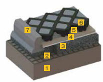
Gravel surfaces installation instructions

The following generic guidance must be read in conjunction with the specific project specification within the contract documents and the design notes below.

  1. Install the optional geogrid, geotextile and/or geomembrane onto the prepared subgrade formation.
  2. Install the specified sub-base layer and optional drainage.
  3. Install any edge restraints which may be specified. Timber, plastic or concrete kerbing are all suitable.
  4. Install the filter/separator geotextile on top of the subbase layer.
  5. Install the specified sand bedding layer to a uniform thickness
  6. Ensure an accurate right-angled CellTrack HD laying pattern by setting-out the site using string-lines. Check the lines regularly for accuracy. Start installing the CellTrack HD pavers. Wherever possible start laying from a right angled corner and progress across the site in rows. The pavers can be installed in a width or lengthwise orientation and cross- bonded if required or appropriate to fit the site. When installing the pavers ensure that the male/female connectors are fully located together. Use protective gloves to avoid abrasions.
  7. CellTrack HD pavers can be cut to fit around obstructions & curves using a hand or power saw. Wherever possible avoid using small cut-pieces less than one-third original size.
  8. When installed, fill the paver cells loosely to the finished level (top of cells) with the specified angular gravel/ aggregate. Remove excess gravel from the surface of the pavers and do not overfill the cells. A single pass with a light vibrating plate machine or roller may be used to firmly bed the pavers and settle the gravel, but do not compact the gravel. It is preferable that the gravel is left just below the top of the cells to reduce its abrasion by traffic. The surface may be trafficked by slow moving plant during the cell-filling process, but care must be taken not to displace the open-celled grids with heavy-treaded or tracked machinery, nor compact the gravel during this operation.
  9. A routine management and maintenance programme to keep the surface in good condition and free of debris and weed growth, will help to sustain the porosity, quality and longevity of the system.

Design notes

Note 1: If the optional geogrid is omitted, the total sub-base layer thickness (‘D’ on Table 1) is typically increased by a minimum of 50%. Selecting an alternative geogrid will require a redesign of the sub-base thickness.

Note 2: Use of E'GRID 30/30 geogrid. If construction traffic axle loads will be greater than 60kN (approximately 6 tonnes), the minimum sub-base thickness over the geogrid shall be 150mm. Maximum sub-base particle size should match minimum subbase thickness but must not exceed 75mm diameter. For sub-base thicknesses of around 100mm, a minimum 37.5mm particle size should be adopted to allow effective installation of the geogrid.

Note 3: Sub-base attenuation utilising a geomembrane and optional geotextile protection, is typically necessary to create a water storage facility and/or a groundwater protection function.

Note 4: A permeable open-graded (reduced-fines) Sustainable Drainage System (SuDS) sub-base layer such as MoT Type 1x, Type 3 or Type 4/40, is preferred. However, where a conventional MoT Type 1 sub-base is to be installed, it is essential that a drainage system is incorporated to assist in the mitigation of issues associated with saturation. This drainage system would typically comprise of a network of perforated pipes or drainage geocomposite.

Note 5: CBR% = California Bearing Ratio: an indicative measurement of subgrade soil strength. Specialist advice should be sought from a suitably qualified person for high-load or critical applications.

Note 6: The SuDS permeable sub-base must be overlaid with a Multitrack 1000 geotextile to provide separation, enhanced water treatment function and prevent migration of the sand bedding layer. The sand bedding must be clean, coarse-grained sand free from silts & clays: it must not be soft building sand or silver sand.

Note 7: The paver fill material should be good quality, free-draining friable topsoil suitable for grass growth and with no contaminants or oversized debris. Amenity grass seed mixture should contain hard-wearing, low fertility and/or drought-tolerant species with the option of a low percentage of clover content if acceptable.

Note 8: The maximum advised gradient for vehicular trafficked applications is 8% (1:12) 5°.

Note 9: When designed in accordance with the recommendations, CellTrack HD complies with BS8300:2009 : “Design of buildings and their approaches to meet the needs of disabled people” – Code of Practice (ISBN 9780 580 57419) & Building Regulations Document ‘M’ Sec. 6

Table 1

APPLICATION / LOAD CBR (%) MOT SUB-BASE THICKNESS (MM) (D) GEOGRID
Fire truck and occasional
HGV access
≥ 6 100 E'GRID 3030
=4 < 6 120 E'GRID 3030
=2 < 4 190 E'GRID 3030
=1 < 2 380 E'GRID 3030
Light vehicle access and overspill car parking ≥ 6 100 E'GRID 3030
=4 < 6 100 E'GRID 3030
=2 < 4 135 E'GRID 3030
=1 < 2 260 E'GRID 3030

Typical sub-base thickness (D) requirements - refer to specific construction drawing

Table 2

  TACTILE VISUAL MECHANICAL (SPT) CBR (5) CU (kN/m2)
Very soft Hand sample squeezes
through fingers
Man standing will sink > 75mm  < 2 < 1 < 25
Soft Easily moulded by finger
pressure
Man walking sinks 50-75mm 2-4 1 25
Medium Moulded by moderate finger
pressure
Man walking sinks 25mm 4-8 1-2 25-40
Firm Moulded by strong finger
pressure
Utility truck ruts 10-25mm 8-15 2-4 40-75
Stiff Cannot be moulded, can be
indented by thumb
Loaded construction vehicle
ruts by 25mm
15-30 4-6 75-100

Field guidance for estimating sub-grade shear strengths

Related products

Stock code Description My Wrekin
GSCELLTRACK/HD100 CellTrack HD 100 (Heavy Duty) 600mm x 400mm x 100mm anthracite grey panel