
Recessed aluminium covers and frames installation guide1. Preparing the surfaceEnsure that there is sufficient depth to accommodate the new frame plus 20-40 mm of bedding mortar, if necessary remove material from the top of the chamber to achieve this, clearing away any loose or flaky material to leave a sound surface for the mortar bed. Take care to avoid any debris entering the chamber. 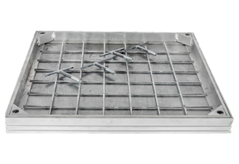 2. Preparing the coverPrise out the 4 plastic bolt protector caps, and retain them for later reuse. 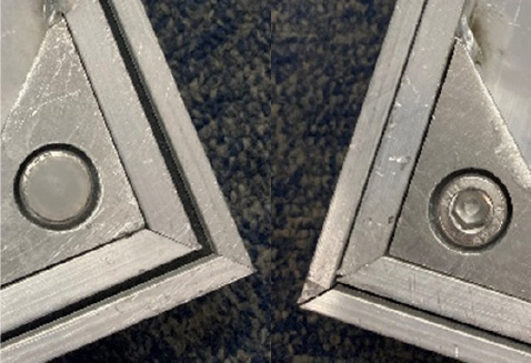
Using the hexagon key provided remove the 4 locking bolts and store safely in a clean environment. 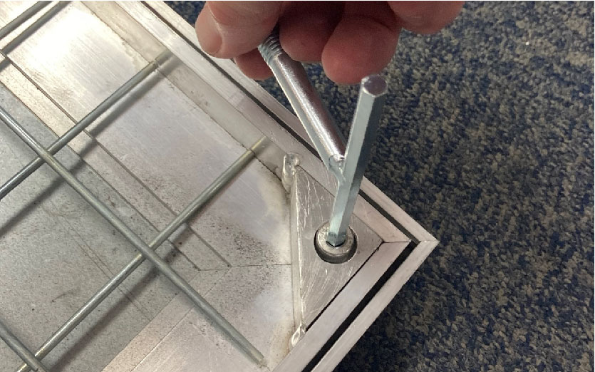
Remove the cover from the frame using the threaded lifting keys provided.   3. TrialTrial position the frame over the manhole chamber, ensuring that it can be positioned in such a way that there is no part overhanging the chamber opening, unsupported framework can lead to premature cover failure. 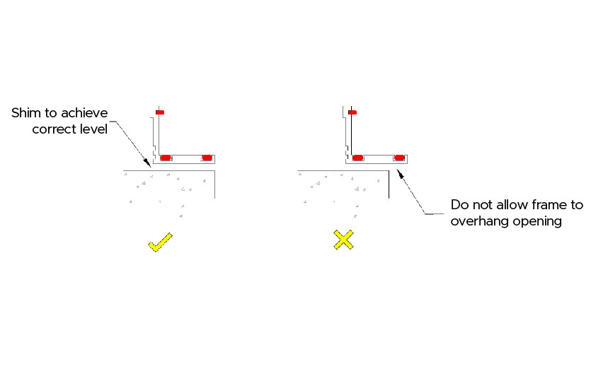 4. Level and laySet the top of the new frame to the required finished floor level, this can be done with a straight edge from the existing finish if available or if not, with a laser level or string lines. Temporarily shim the frame at the correct height to gauge the depth requirement of the mortar bed. Lay down a mortar bed large enough to fully support the frame, leaving it slightly proud for tamping. 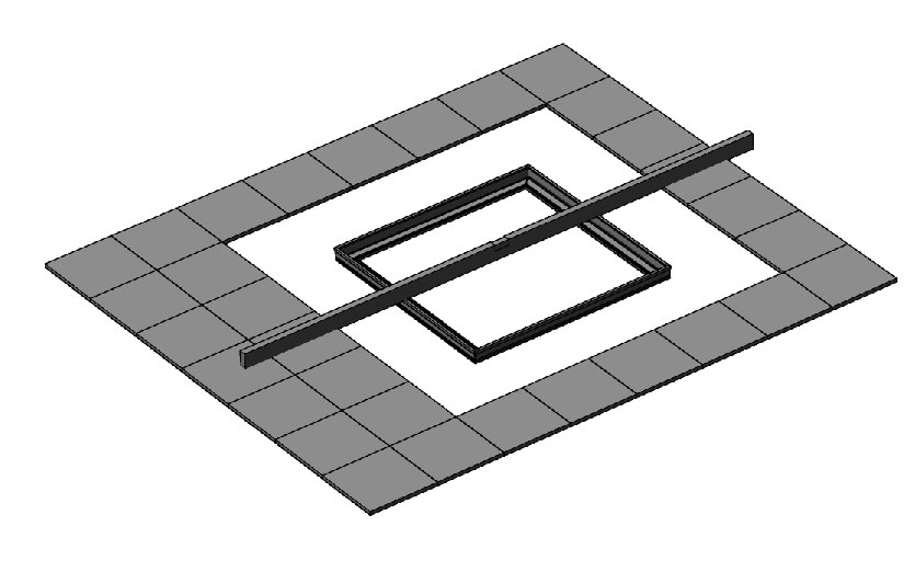 5. TampPosition the frame on the mortar bed in its previously established location and carefully insert the cover. Loosely replace the 4 locking bolts but do not tighten them at this stage, doing so may distort the frame. Tamp down until the top of the cover and frame sits at the required finished level on all sides. Check that the cover sits in the frame with no rock and that the top of the cover and frame is level, making any necessary adjustments to the bedding to achieve a good, non-rock fit. 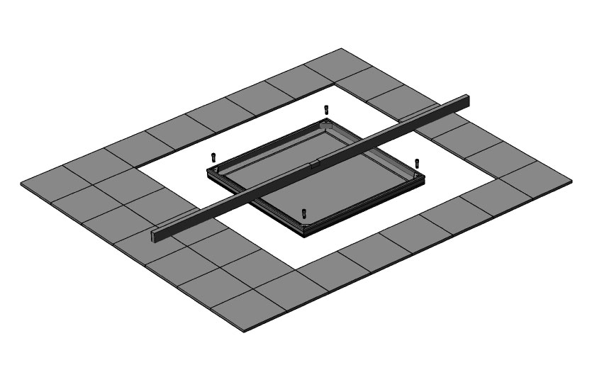 6. SetAllow the mortar to stabilise and then carefully remove the locking screws and cover. Point the inside of the frame and remove any excess mortar, also haunch around the outside of the frame leaving sufficient depth for any subsequent finishes (vinyl, tiles etc.). Allow the mortar bed to fully cure before proceeding. 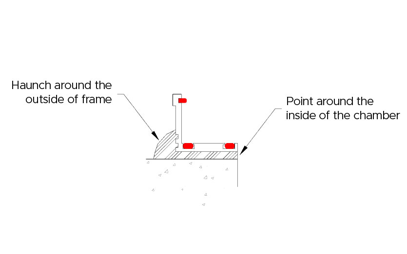 7. TapeReturn the cover to the frame and refit the locking bolts. Tape across the top edges of the cover, frame and lifting eyes to prevent ingress of debris and damage to the surface when backfilling 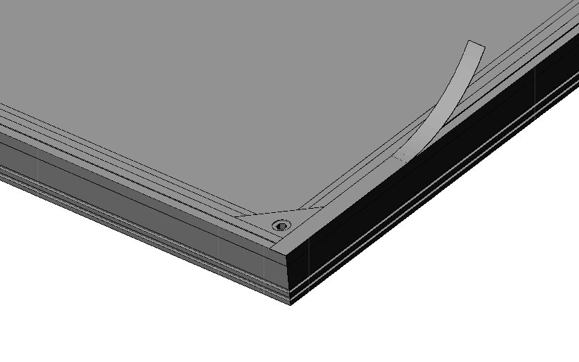 8. Screed - FrameScreed/concrete up to the outside of the frame, leaving depth for subsequent adhesives and floor finishes if required.  9. Screed - CoverScreed/concrete the inside of the cover recess, again leaving depth for subsequent floor finishes. A stepped strickle is easily made and assists with filling the cover. Note: In instances where there is insufficient depth to apply a screed sub-base prior to finishing, lay the flooring directly onto a mortar bed. This is particularly applicable to external installations (Fig 12 and fig 13)   Fig 12 – External installation with fresh mortar bed. 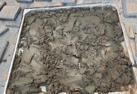 Fig 13 – External paving set directly on mortar bed. 10. CompleteRemove the protective tape from the top edges, fully tighten the locking bolts and replace the plastic protector caps to complete the installation. 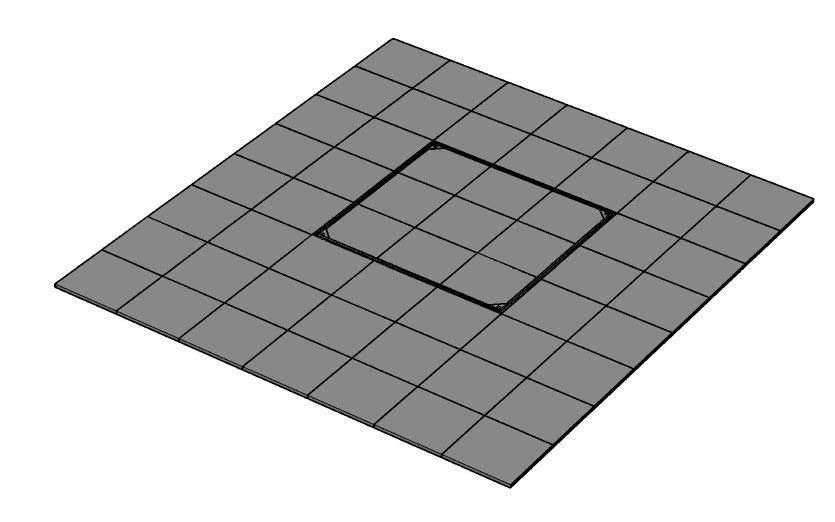 Related pagesRelated products
| |||||||||||||||||||||||||||||||||||||||||||||||||||||||||||||||||||||||||||||||||||||||||||||||||||||||||||||||||||||||||||||||||||||||||||||||||||||||||||||||||||||||||||||||